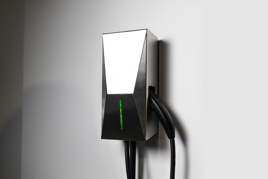
Component List
- Enclosure

- Controller PCB + LCD

- Power Relay

- GFCI Current Transformer

- Current Measurement Transformer

- Cable Glands

- Input Power Cable

- Output Power Cable

Step by Step Procedure
- Mount the Controller PCB inside the enclosure

- Mount the Power Relay and Current Transformers inside the enclosure

- Install the cable glands for the input and output power cables

- Run the input power cable through the left cable gland and terminate as follows: ground to mounting plate, line and neutral to input side of power relay

- Connect the AC connector - J2 on the controller to the power relay input and output terminals

- Run the output cable through the right cable gland and terminate as follows: ground to mounting plate, line and neutral trough the GFCI current transformer, line to power relay output terminal, neutral only through current measurement transformer and to output terminal of power relay, pilot wire to J5 connector on controller PCB. Note that the proximity wire is not connected

- Connect the controller to the Relay coil and current transformers. The current transformers are connectorized and plug into J7 and J8. The coil of the power relay goes to connector J3

- Install Lid, Power up and Charge


